The former article showed that the installation of an LFP battery bank is different from the lead acid. Here we describe how we dealt with these differences on the Ya. Take your advantage of it.
Prevent exchange costs
Firstly, you’d better not do what we did on ‘Ya’. We first chose for a lead acid bank and now we exchanged it for LFP. You’d better choose for LFP straight away. We now had to throw away the old lead acid devices, e.g., our main hand battery switch of over 100 Euros, a volt meter, and much more. And, a lead acid bank costs more space and has more weight. In the first place, it has cost a lot of money to realize this. And now with the LFP bank, we have two water and air tight compartments left over. It is all pity money spent.
Check the compatibility of BMS, CAN bus and charger
One of the beauties of the BMS that it manages the whole charging process. It controls all these little circuit boards in such a way, that a ‘difficult’ cell gets more, an ‘easy’ cell gets less energy. Hence, they all get charged equally, until every cell is at its maximum at exactly 3.65Volt. This last phase is called the balancing phase. Then the charging energy is very little, but very precise. Therefore, the BMS must be able to regulate your charger precisely. It asks for a good communication.
Then you need a CAN bus between the BMS and the charger. You buy the thing from your charger supplier. In case of ‘Ya’ we have a Studer xTender (inverter and charger). Studer delivers the xCom-CAN with a variety of protocols and communication speeds, so no problem for us. But, make sure that there is one that your BMS can communicate with. Make sure, before you buy the BMS (or the charger).
The professional installer like in our case EV Europe, can configure it all.
Full-automatic system requires solid, reliable work
Full automation sounds beautiful, but a BMS with incorrect feeds, can fully automatically damage your equipment. We made the next mistake.
On ‘Ya’ the BMS got its feed from our 12 Volt service battery, an AGM battery already of age. It also feeds the anchor winch. The voltage drops were big, so the BMS switched the main relay switch on and off and on and off, about 5 times per seconds. This created a chaotic flow of currents running up and down the various charge devices. In one anchor maneuver, these freak currents blew the fuses of the solar MPPT and converter, and the wind generator’s MPPT died.
We did two things to solve this:
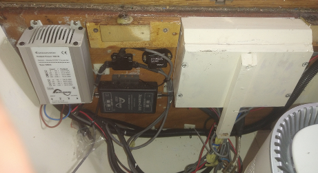
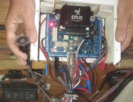
- We eliminated the cause by giving the BMS a separate 12V power supply. Many choose for a battery, but we installed the higly reliable Studer DC/DC converter. The feed comes straight from the 48 Volt battery bank, through this DC/DC converter feeding the BMS and all its equipment, such as the relay switch.
2. We contained the possible impact, by:
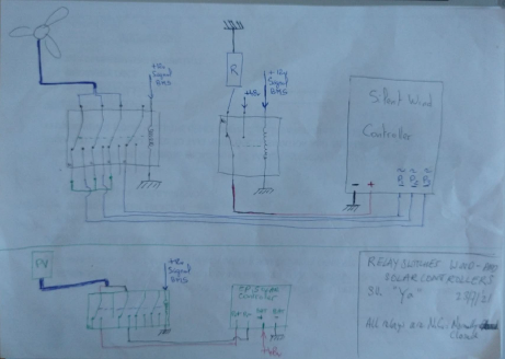
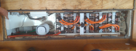
– Installing a relay switch on the output of each of the three charging devices (solar, solar and wind).
– Connecting a relay on the input of the wind MPPT. This works as a short circuit, to slow down the wind turbine.
– Installation of an extra resistor on the output side of the wind turbine, just in case the turbine runs another 2 or three rotations and generating a last bit of power. This would flow into that resistor.
So, now when the BMS switches off the main relay, it also switches off the charging devices and no freak current can enter any device or electronics.
This is also nice if someone is working on the electricity: there is really no power on the net, so no risk of fire or damage when working.
Dry compartments
Main cause of failures of electrics and electronics is the bad, corroded contact, mostly caused by moist and dirt. On a sea going yacht, you have a lot of moist and salt. Connections can easily rot away in that environment. So we climatized this environment of the battery bank and devices.
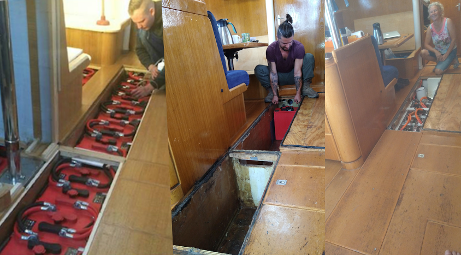
The lead acid battery bank was put in air tight compartments in the bilge. Now we put LiFePO4cells in it. And, these cells are so small, they don’t take much space. So there was plenty space to make a circular ventilation duct through the compartments, with a dehumidifier. Now, once a day the little 5-Watt ventilator and the 40-Watt dehumidifier run for an hour. It keeps both battery compartments, including the BMS, CAN bus, 48/12 DC-DC converter, circuit boards and all connections, extremely dry.
Bypassing contactor manually for charging purposes
It is rare, but suppose you get this scenario.
You are at sea and for whatever reason the battery bank is low. And then, there is no sun and no wind, for days and days. Meanwhile you cook, use navigation equipment, so the bank gets lower and lower. Then, one night, the voltage becomes too low and so the BMS disconnects the Contactor (main switch battery bank).
Then in the morning, the sun starts shining. Since the switch is off, the solar power feed is disconnected from the battery bank, so it won’t charge. Now you are in a Catch 22.
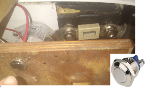
Therefore, we have a little button that switches on the contactor and other relay switches, so the energy can flow into the bank. You have to push actively. When you let it go, the circuit is broken again. But that pushing won’t take long because we are in a steep curve, where a little bit of energy is already enough to quickly raise the voltage. And if something else is wrong, the push button makes you very aware of that and you have full attention to the system.
Some extra beeps
The Battery Management System is measuring so much, and is so well in full control, that it invited us to take profit of this advantage. Naturally you get readings on your display when something is going wrong, and even with pre-warnings. But we liked to have some hard signals you can hear. So, there is a high beep now, when the battery bank’s voltage gets too high. There is a low beep when the voltage drops too low and the battery bank is almost empty. And we have another low beep as a pre warning if the battery bank has only 10% left to use. Very nice that you are pre warned before you are confronted with dead engines when you are maneuvering in a harbor.
It just takes some extra hours for installing and mounting the cables, for the rest it is just a matter of some computer settings in the configuration.
The usual extra attention to the alternator
A wind turbine contains an alternator and this is one that you can stop. But if you have a diesel engine with an alternator to charge your batteries, you have the usual problem (next to all problems there are with combustion engines).
The general problem of alternators: you cannot disconnect the output from the battery bank, because the diodes of the alternator would blow up. So, you have to stop the alternator before. When you have a combustion (diesel) engine, you first have to stop the engine before you turn the main battery switch to OFF.
When you take an LFP bank with a BMS, and so an automatic relay switch, the contactor (main switch) is automatic. Whenever there is a chance of fire, or ruining the batteries, because of under or over voltage, it will disconnect automatically.
There are some solutions.
- The alternator feed bypasses the main switch. Many boats have this already. The problem is, when you work on the battery bank with the main switch on OFF, and the engine starts running, there is still electricity on the net. And the other way around: when a normal user (like a leisure skipper) switches off the main switch for whatever reason (chance on fire?), he presumes to be safe and have an power free circuit. But, when using the engine, there is electricity again. So again a risk on fire?
- Modify the alternator, so the field current is stopped, and the alternator stops charging.
- The generations after you will tell you that the best solution is to stop combusting CO2, NOx, SOx and fine dust into the air, and take electric engines for your leisure. They are also much more reliable too. See this article
This is the last of the 4 articles about LFP/LiFePO4 battery bank compared to lead acid.
Here you find a more technical description of an installation of a service pack.